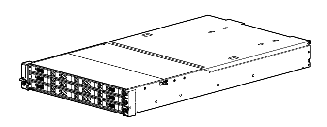
Setup Overview
for the HPE Apollo 4200 Gen9 Server
Before you begin
- For safety, environmental, and regulatory information, see Safety and Compliance Information for Server, Storage, Power, Networking, and Rack Products on the Hewlett Packard Enterprise website.
- Select an installation site that meets the detailed installation site requirements described in the server user guide.
- Unpack the server shipping carton, and locate the materials and documentation necessary for installing the server.
- Verify operating system support—For information about operating systems supported by ProLiant servers, see the operating system support matrices.
For more pre-installation information, see the HPE Apollo 4200 Gen9 Server User Guide.
Component identification
Front panel components
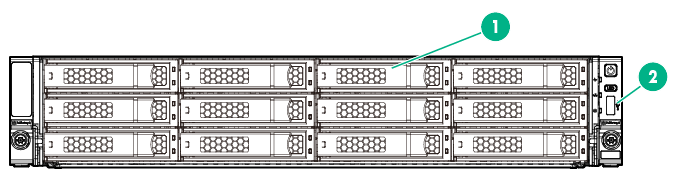
- LFF chassis
Item
Description
1
LFF hot-plug drives
2
USB 2.0 connector
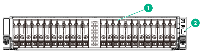
- SFF chassis
Item
Description
1
SFF hot-plug drives
2
USB 2.0 connector
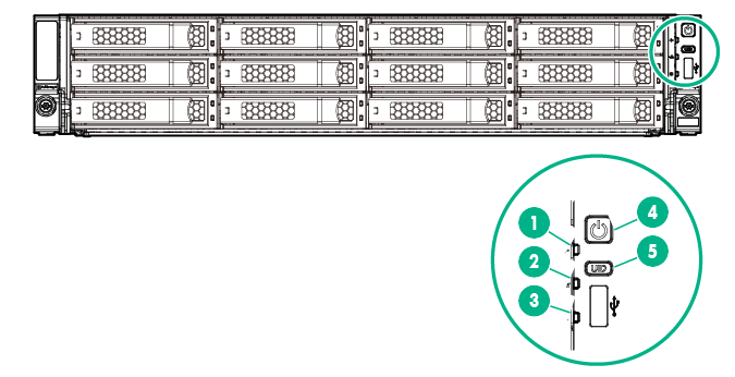
Front panel LEDs and buttons
Item |
Description |
Status |
|---|---|---|
1 |
Health LED1 |
Solid green = Normal Flashing green (1 flash per sec) = iLO is rebooting Flashing amber = System degraded2 Flashing red (1 flash per sec) = System critical2 |
2 |
NIC status LED1 |
Solid green = Link to network Flashing green (1 flash per second) = Network active Off = No network activity |
3 |
Front drive health/thermal LED |
Solid green = Drives supported by the SAS expander are functional.3 Solid amber = Failure or predictive failure of one or more drives supported by the SAS expander.3 Flashing amber (1 flash per sec) = The temperature sensor in one or more front drives is about to reach the thermal threshold. Immediately slide the front drive cages back into the chassis and keep them there until the LED turns green.4 Off = No power present5 |
4 |
Power On/Standby button and system power LED1 |
Solid green = System on Flashing green (1 flash per second) = Performing power on sequence Solid amber = System in standby Off = No power present 5 |
5 |
UID button/LED1 |
Solid blue = Activated Flashing blue:
Off = Deactivated |
1 When these four LEDs flash simultaneously, a power fault has occurred. For more information, see "Power fault LEDs" in the HPE Apollo 4200 Gen9 Server User Guide.
2 If the health LED indicates a degraded or critical state, review the system IML or use iLO to review the system health status.
3 This LED behavior applies to all front drives, as well as to the rear drives connected to the front drive cage 2 backplane.
4 This LED behavior depends on the iLO 08-HD Max sensor reading. For more information, see "Front drive thermal LED" in the HPE Apollo 4200 Gen9 Server User Guide.
5 Facility power is not present, power cord is not attached, no power supplies are installed, power supply failure has occurred, or the front I/O cable is disconnected.
Rear panel components
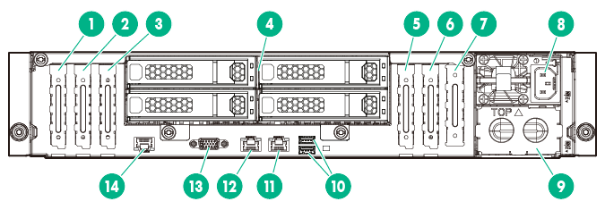
- Rear panel with the four-bay LFF hot-plug rear drive cage option
Item
Description
1
PCIe3 x16 (16, 8, 4, 1) slot 7 for low-profile, standup expansion board1
2
PCIe3 x8 (8, 4, 1) slot 6 for low-profile, standup expansion board1
3
PCIe3 x16 (16, 8, 4, 1) slot 5 for low-profile, standup expansion board1
4
LFF hot-plug drives
5
PCIe3 x16 (16, 8, 4, 1) slot 2 for low-profile, standup expansion board or riser cage options2
6
PCIe3 x8 (8, 4, 1) slot 1 for low-profile, standup expansion board2
7
FlexibleLOM slot2
8
Hot-plug power supply bay 1
9
Hot-plug power supply bay 2
10
USB 3.0 connectors
11
NIC 1/shared iLO connector
12
NIC connector 2
13
Video connector
14
Dedicated iLO management connector (optional)
1 The PCIe expansion slots 5-7 are associated with processor 2.
2 The PCIe expansion slots 1-4 and the FlexibleLOM slot are associated with processor 1.
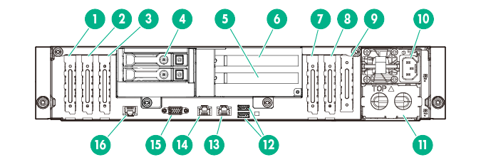
- Rear panel with the two-bay SFF hot-plug rear drive cage and two-slot PCI riser cage options
Item
Description
1
PCIe3 x16 (16, 8, 4, 1) slot 7 for low-profile, standup expansion board1
2
PCIe3 x8 (8, 4, 1) slot 6 for low-profile, standup expansion board1
3
PCIe3 x16 (16, 8, 4, 1) slot 5 for low-profile, standup expansion board1
4
SFF hot-plug drives
5
PCIe3 x8 (8, 4, 1) riser slot 4 for full-height, half-length expansion board2
6
PCIe3 x8 (8, 4, 1) riser slot 3 for full-height, half-length expansion board2
7
PCIe3 x16 (16, 8, 4, 1) slot 2 for low-profile, standup expansion board or riser cage options2
8
PCIe3 x8 (8, 4, 1) slot 1 for low-profile, standup expansion board2
9
FlexibleLOM slot2
10
Hot-plug power supply bay 1
11
Hot-plug power supply bay 2
12
USB 3.0 connectors
13
NIC 1/shared iLO connector
14
NIC connector 2
15
Video connector
16
Dedicated iLO management connector (optional)
1 The PCIe expansion slots 5-7 are associated with processor 2.
2 The PCIe expansion slots 1-4 and the FlexibleLOM slot are associated with processor 1.
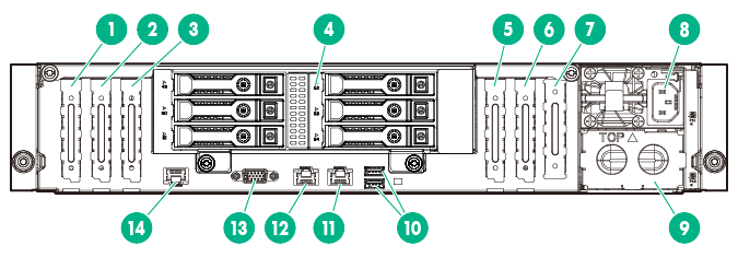
- Rear panel with the six-bay SFF hot-plug rear drive cage option
Item
Description
1
PCIe3 x16 (16, 8, 4, 1) slot 7 for low-profile, standup expansion board1
2
PCIe3 x8 (8, 4, 1) slot 6 for low-profile, standup expansion board1
3
PCIe3 x16 (16, 8, 4, 1) slot 5 for low-profile, standup expansion board1
4
SFF hot-plug drives
5
PCIe3 x16 (16, 8, 4, 1) slot 2 for low-profile, standup expansion board or riser cage options2
6
PCIe3 x8 (8, 4, 1) slot 1 for low-profile, standup expansion board2
7
FlexibleLOM slot2
8
Hot-plug power supply bay 1
9
Hot-plug power supply bay 2
10
USB 3.0 connectors
11
NIC 1/shared iLO connector
12
NIC connector 2
13
Video connector
14
Dedicated iLO management connector (optional)
1 The PCIe expansion slots 5-7 are associated with processor 2.
2 The PCIe expansion slots 1-4 and the FlexibleLOM slot are associated with processor 1.
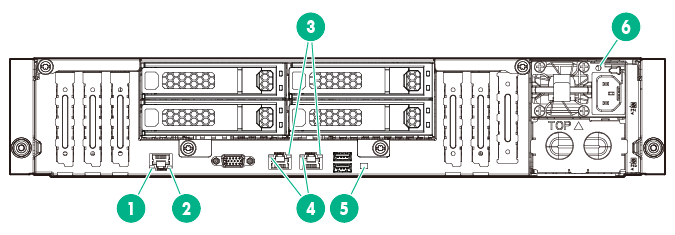
Rear panel LEDs
Item |
Description |
Status |
|---|---|---|
1 |
Dedicated iLO activity LED |
Solid green = Link to network Flashing green = Network active Off = No network activity |
2 |
Dedicated iLO link LED |
Green = Network link Off = No network link |
3 |
NIC activity LED |
Solid green = Link to network Flashing green = Network active Off = No network activity |
4 |
NIC link LED |
Green = Network link Off = No network link |
5 |
UID LED |
Solid blue = Activated Flashing blue:
Off = Deactivated |
6 |
Power supply LED |
Solid green = Normal Off = One or more of the following conditions exists:
|
Removing the shipping screws from the front drive cages
The front drive cages are secured to the chassis by shipping screws upon product delivery. The location and number of these shipping screws depend on how the server was shipped during product delivery. Remove these shipping screws before the first time installation of the server into the rack. This will allow the front drive cages to be extended out of the chassis.
Do one or both of the following steps to remove the shipping screws securing the front drive cages:
- Remove the shipping screws on the sides of the chassis.
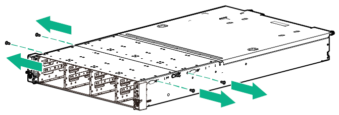
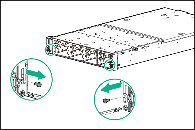
- Remove the shipping screws on the rack ears:
- If installed, remove the security bezel.
- Remove the shipping screws on the rack ears.
Install server options
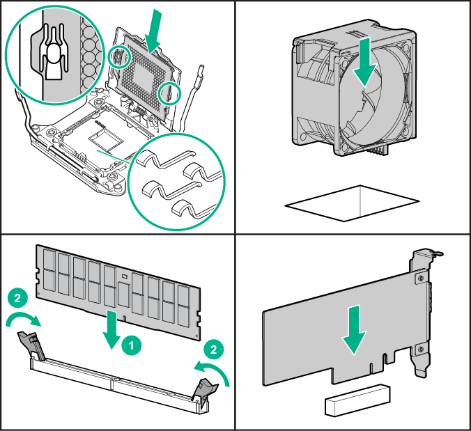
For options installation information, see the documentation that ships with the option. For server‑specific information, see the HPE Apollo 4200 Gen9 Server User Guide.
Install the server in the rack
Before installing the server, be sure that you understand the following warnings and cautions.
|
WARNING: To reduce the risk of personal injury or damage to the equipment, be sure that:
|
|
WARNING: To reduce the risk of personal injury or equipment damage when unloading a rack:
|
|
WARNING: To reduce the risk of personal injury or damage to the equipment, adequately stabilize the rack before extending a component outside the rack. Extend only one component at a time. A rack may become unstable if more than one component is extended. |
|
WARNING: When installing a server in a telco rack, be sure that the rack frame is adequately secured at the top and bottom to the building structure. |
|
WARNING: This server is very heavy. To reduce the risk of personal injury or damage to the equipment:
|
|
WARNING: To reduce the risk of electric shock or damage to the equipment:
|
|
CAUTION: Always plan the rack installation so that the heaviest item is on the bottom of the rack. Install the heaviest item first, and continue to populate the rack from the bottom to the top. |
|
CAUTION: Protect the server from power fluctuations and temporary interruptions with a regulating uninterruptible power supply. This device protects the hardware from damage caused by power surges and voltage spikes and keeps the system in operation during a power failure. |
|
CAUTION: Do not operate the server for long periods with the front drive cages extended. When the front drive cages are extended while the server is powered on, do one of the following:
|
To install the server in the rack:
- Install the server rack rail in the rack. See the documentation that ships with the HPE 2U Shelf-Mount Adjustable Rail Kit.
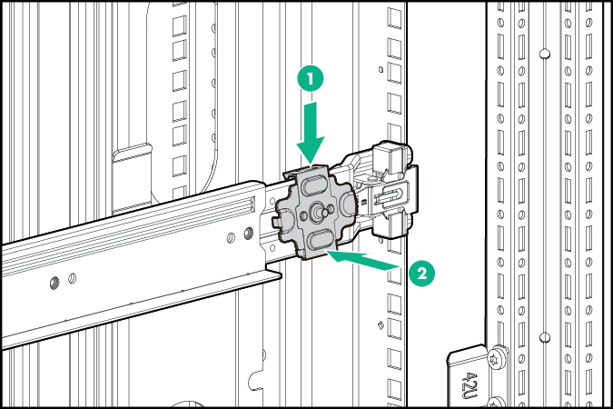
- The chassis retention brackets help to stabilize the server when the front drive cages are extended.
The illustration below shows the rack rail with the shelf portion highlighted in gray.
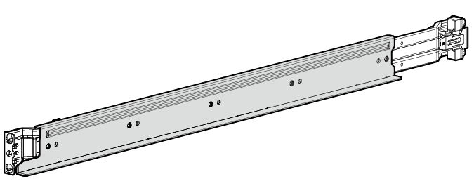
Install the chassis retention brackets on the non-shelf portion of the rack rail.
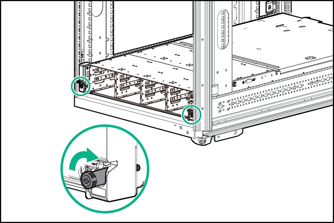
- Install the server into the rack.
- Tighten the rack ear thumbscrews.
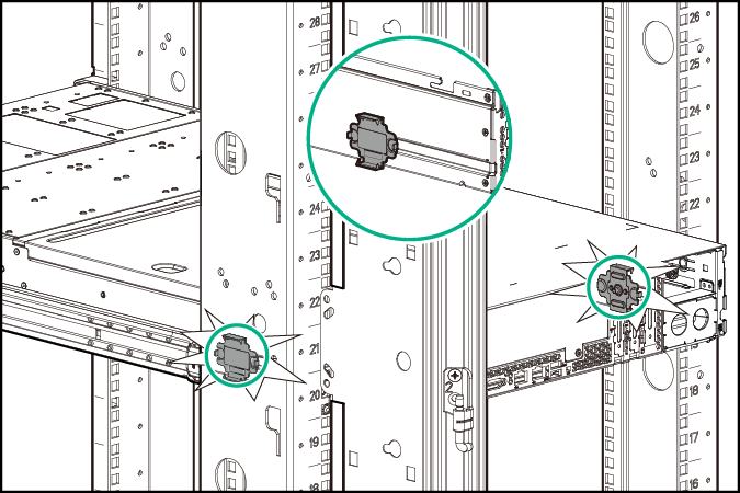
- Make sure the pins on the chassis retention brackets slot into the notches located on both sides of the chassis.
Install drives and power input modules
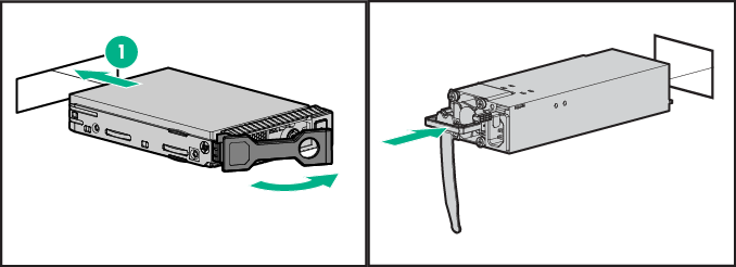
For options installation information, see the documentation that ships with the option. For server‑specific information, see the HPE Apollo 4200 Gen9 Server User Guide.
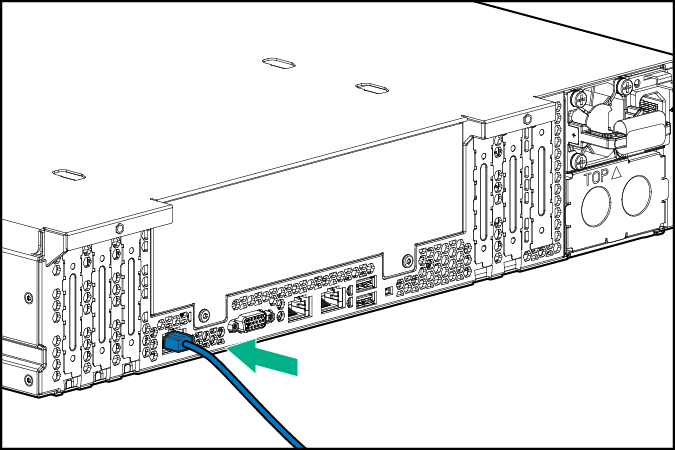
Connect cabling and power cords
- Connect the iLO management cabling.
The dedicated iLO connector shown in the image is an optional component. If you do not have this option installed, the iLO management connection will be routed through the NIC 1/shared iLO connector.
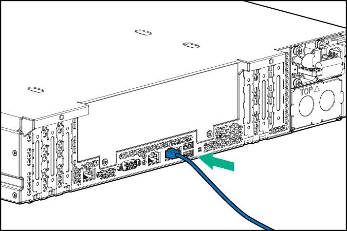
- Connect the network cabling.
- Connect the power cord to the power input module.
- AC power input module
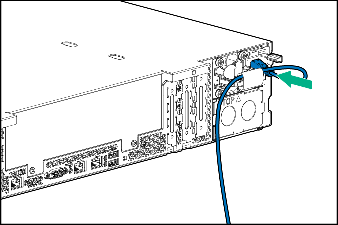
- DC power input module
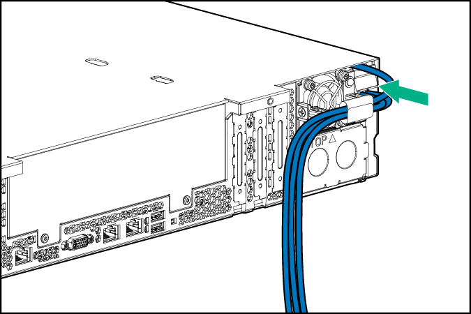
- AC power input module
For more information about cabling the system, see the HPE Apollo 4200 Gen9 Server User Guide.
Power up and select boot options
On servers operating in UEFI Boot Mode, the boot controller and boot order are set automatically.
- Press the Power On/Standby button.
- During the initial boot:
- To modify the server configuration ROM default settings, press the F9 key in the ProLiant POST screen to enter the UEFI System Utilities screen. By default, the System Utilities menus are in the English language.
- If you do not need to modify the server configuration and are ready to install the system software, press the F10 key to access Intelligent Provisioning.
For more information on automatic configuration, see the UEFI documentation on the Hewlett Packard Enterprise website.
Install the system software
This ProLiant server does not ship with provisioning media. Everything needed to manage and install the system software and firmware is preloaded on the server.
To operate properly, the server must have a supported operating system. Attempting to run an unsupported operating system can cause serious and unpredictable results. For the latest information on operating system support, see the Hewlett Packard Enterprise website.
Failure to observe UEFI requirements for ProLiant Gen9 servers can result in errors installing the operating system, failure to recognize boot media, and other boot failures. For more information on these requirements, see the HPE UEFI Requirements on the Hewlett Packard Enterprise website.
To install an operating system on the server, use one of the following methods:
- Intelligent Provisioning—For single-server deployment, updating, and provisioning capabilities.
To install an operating system on the server with Intelligent Provisioning (local or remote):
- Connect the Ethernet cable between the network connector on the server and a network jack.
- Press the Power On/Standby button.
- During server POST, press F10.
- Complete the initial Preferences and Registration portion of Intelligent Provisioning.
- At the 1 Start screen, click Configure and Install.
- To finish the installation, follow the onscreen prompts. An Internet connection is required to update the firmware and systems software.
- Insight Control server provisioning—For multi-server remote OS deployment, use Insight Control server provisioning for an automated solution. For more information, see the Insight Control documentation on the Hewlett Packard Enterprise website.
For additional system software and firmware updates, download the Service Pack for ProLiant from the Hewlett Packard Enterprise website. Software and firmware must be updated before using the server for the first time, unless any installed software or components require an older version.
For more information, see the "Keeping the system current" section in the HPE Apollo 4200 Gen9 Server User Guide
For more information on using these installation methods, see the Hewlett Packard Enterprise website.
Register the server
To experience quicker service and more efficient support, register the product at the Hewlett Packard Enterprise Product Registration website.
Additional information
For more information, see the HPE Apollo 4200 Gen9 Server documentation in the Hewlett Packard Enterprise Information Library.
For important safety, environmental, and regulatory information, see Safety and Compliance Information for Server, Storage, Power, Networking, and Rack Products, available at the Hewlett Packard Enterprise website.
Hewlett Packard Enterprise is committed to providing documentation that meets your needs. To help us improve the documentation, send any errors, suggestions, or comments to Documentation Feedback. When submitting your feedback, include the document title, part number, edition, and publication date located on the front cover of the document. For online help content, include the product name, product version, help edition, and publication date located on the legal notices page.
Part number: 807314-002
April 2016
Edition: 2